
A computer comprises of two components: hardware and software.
Computer hardware refers to the physical components of a computer system, such as the central processing unit (CPU), memory, hard drive, motherboard, and peripherals like keyboards, mice, and monitors. Hardware components work together to allow the computer to function properly and carry out tasks according to software instructions. Hardware can be upgraded, replaced, or repaired, and it can be manufactured by various technology companies. Hardware can range from personal computers and laptops to servers, mobile devices, and other electronic equipment.
Computer software refers to a collection of instructions or programs that are designed to perform specific tasks on a computer system. This can include operating systems, applications, utilities, and games. Software is what enables users to interact with and make use of the hardware, and it can be written in various programming languages. Software can be installed, updated, and uninstalled on a computer system, and it can be developed by individuals, organizations, or software companies.
Next is a video that further explains these two components.
Classical Gates- The "NOT" Gate
We just learned about bits. Bits can be stored using anything that can take two different values, like 0 or 1, or up or down, blue or yellow, etc.
But what are bits? How are they made? How do we distinguish between a 1 bit and 0 bit? Fundamentally, bits are just our interpretation of electricity moving through wires or being stored on a component. We set a threshold for a given part of the circuit and measure the current or voltage. If the measured value is higher than that threshold, we call it 1, and if it's lower we call it 0. There are other ways that we can describe the same process.

The 1 bit can also be described as an arrow pointing upwards, or a "true" statement, while the 0 bit can be described with a downward arrow or a "false" statement. When we want to change a bit in some way, we pass it through a gate.
Gates are logic statements like NOT, OR, AND, etc. You may not know it, but we use logic gates all the time. Here is an example:
"I have a sweater, so I am not cold".
The "not" in this sentence is the gate. You can break it down into smaller pieces of information and ask if each one is true or false.
Do I have a sweater? True.
Am I cold? False.
We can also change examine the other possible case:
Do I have a sweater? False.
Am I cold? True.
In this case, the two statements have to be opposites. If the first part is true, the second part must be false, and vice versa.
Computers also have a NOT gate! It has exactly the same function as "not" in speech.
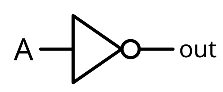
The NOT gate changes 0 to 1, and 1 to zero. This gate is usually shown as the symbol below. The NOT gate only takes one input. The input is shown on the left side and the output on the right side.
For example, when the NOT gate is applied on a bit with the value 1, the output will be 0 (and vice versa):

Or equally when the input to a NOT gate is true, the output will be false:
Classical Gates- The "AND" Gate

As we discussed before, we can describe bits using True/False. Doing this, we get the following truth table.

Classical Gates- The "OR" Gate

Below is a truth table for a 2 input OR gate; however, OR gates can take multiple inputs. For example, consider how the table would work if you had three inputs.

Classical Logic Circuits
When we do standard addition, we sometimes have to carry digits. For instance, adding 5+7 gives us 12. Even though we fed in two single digit numbers, our result was two digits. This also happens in binary: if the sum of two digits is greater than 2, we have to carry it to the next column.

Notice that when you do the addition for the first column (on the right-hand side), you only need two pieces of input: the bit from the top number and the bit from the bottom number. However, for every column after that, you need three pieces of input: the top bit, the bottom bit, and another bit that tells you whether anything was carried over from the previous column. We will call this extra bit the carry bit.
Half Adder Circuit

One of the most important tools for understanding logic circuits is called a truth table. A truth table lists all the possible inputs to a circuit along with the corresponding output. Below is the truth table for the half adder circuit, but some of the outputs are missing! See if you can fill in the blanks using your knowledge of classical gates.'

Now let's build this circuit and try experimenting with it!

Build this circuit in Logic.ly and fill in the truth table below. Does it do the same thing as an XOR gate?

Next, try replacing the XOR gate in your half adder circuit. Check that you get the same output as before.


0 Comments